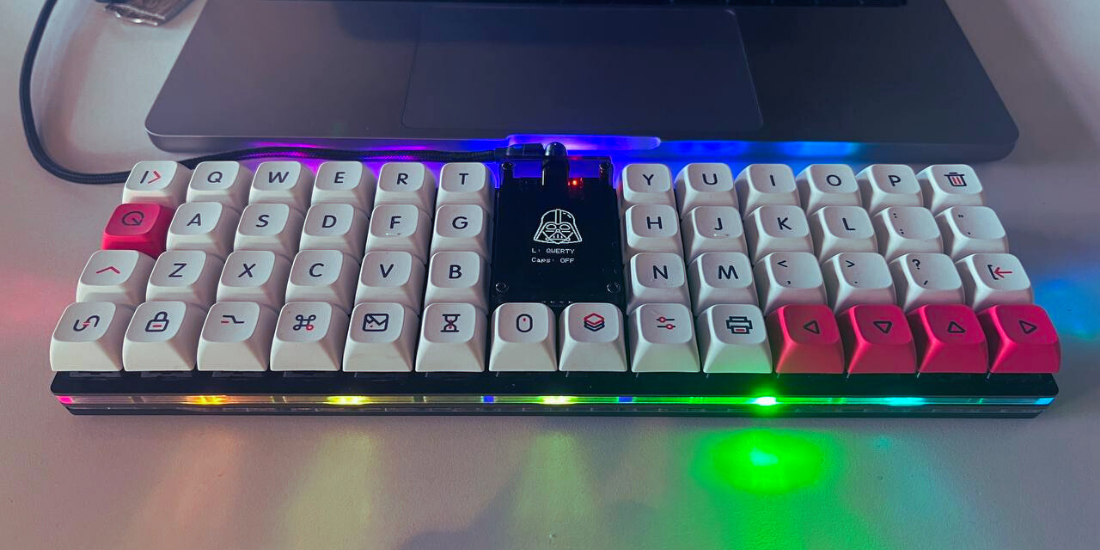
Yakamoz Keyboard Build Guide
Yakamoz is a special Turkish word which is used when the moonlight shines on the sea, ocean etc.. There is no such a direct translation in English.
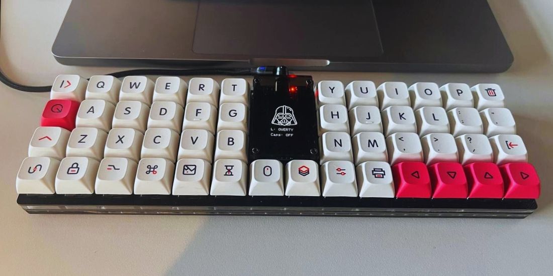
Yakamoz is a 50-key ortholinear keyboard, powered by a Raspberry Pi Pico. It consists of 1U keys with an OLED display, buzzer, trackball (optional) and RGB leds. It also supports hotswap, which means you can easily change Change with Cherry MX compatible switches.
An ortholinear keyboard is a type of keyboard where the keys are aligned on a flat grid. Ortholinear keyboards are more compact than traditional keyboards, typically available in 40% and 60% keyboard sizes that do not include functions and keys. In this guide we will build a 60% keyboard. You will find all information about the needed circuit board, acrylic case and modified QMK firmware on this site.
Features
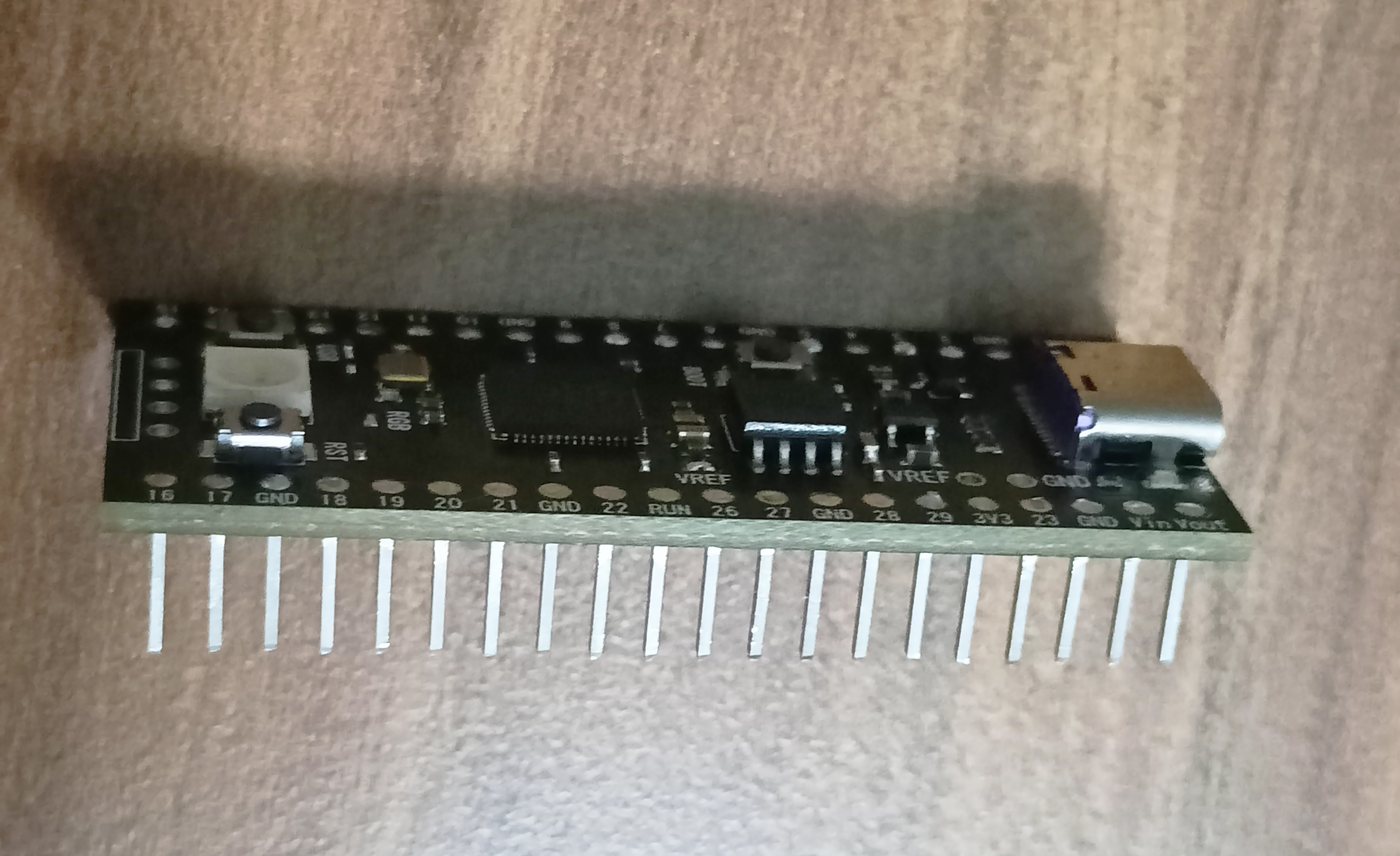
- Raspberry Pi Pico Board RP2040
- USB Type-C connector (pico clone)
- More memory, storage and clock than pro micro based boards
- Fully supported by QMK Firmware
- Fully supported by ZMK Firmware
- Kaihl Hot-swap sockets for MX compatible switches
- Buzzer (optional) (It can play 8bit sounds, starting sounds, keystrokes, etc)
- OLED displays (optional) (SH1107 128x64 pixel or SSD1306 64x128 pixel)
- Trackball (optional)
- Underglow RGB with 12 SMD SK6812-SIDE-A(4020) LEDs
- Acrylic plate case (Designed with a sandwich-style plate/case as part of the design)
Bill of Materials
| Qty | Part Descript | Notes |
|---|---|---|
| 1 | Main PCB | Gerber file: https://github.com/ozkan/Yakamoz |
| 1 | Switch plate PCB | (PCB Thickness 1.2mm) Gerber file: https://github.com/ozkan/Yakamoz |
| 50 | MX Compatible Key Switch | 3pin or 5pin |
| 50 | MX Compatible Keycap (1U) | |
| 1 | Raspberry Pi Pico Board RP2040 | |
| 1 | IIC Serial 4pin OLED Display Module (SH1107 128x64 pixel or SSD1306 64x128 pixel) | If you plan to use trackball you should use ‘SSD1306 64x128’ |
| 12 | SK6812-SIDE-A(4020) LED Chip | |
| 1 | Pimoroni trackball | Optional |
| 50 | Kaihl Hot-swap sockets | for MX compatible switches |
| 50 | 1N4148 SOD123 Diodes | |
| 1 | Passive buzzer 12*9.5mm | Optional |
| 2 | 20pin single row pin female header socket | Pitch 2.54mm (for pico board) |
| 1 | 4pin single row pin female header socket | Pitch 2.54mm (for oled) |
| 1 | 5pin single row pin female header socket | Pitch 2.54mm (for trackball) |
| 1 | 5pin round hole pin female header | 2.0MM/2.54MM Pitch (for switch plate) |
| 1 | 5pin round hole pin male header | 2.0MM/2.54MM Pitch (for switch plate) |
| 8 | M2x7mm Standoff/Spacer | |
| 4 | M2x10mm Standoff/Spacer | |
| 24 | M2x6mm Screw | |
| 8 | Silicone Bumpers | |
| 1 | Upper Middle Plate (4mm transparent acrylic) | Dxf file: https://github.com/ozkan/Yakamoz |
| 1 | Lower Middle Plate (2mm acrylic) | Dxf file: https://github.com/ozkan/Yakamoz |
| 1 | Bottom Plate (3mm acrylic) | Dxf file: https://github.com/ozkan/Yakamoz |
| 1 | Oled Cover (Transparent or smoked acrylic) | Dxf file: https://github.com/ozkan/Yakamoz |
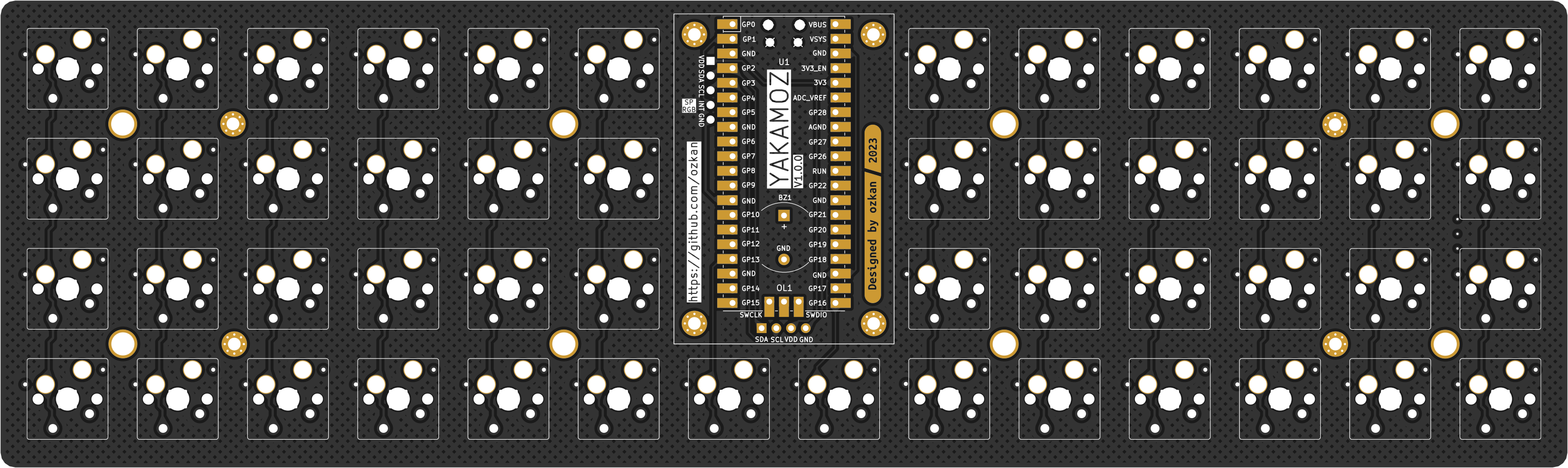
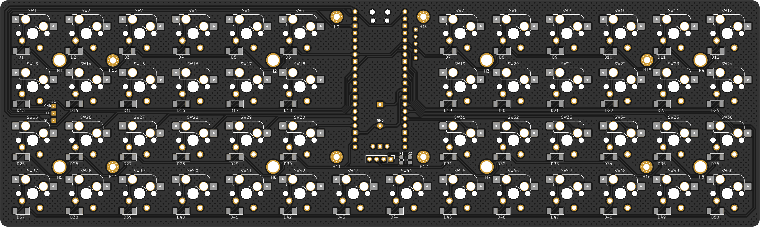
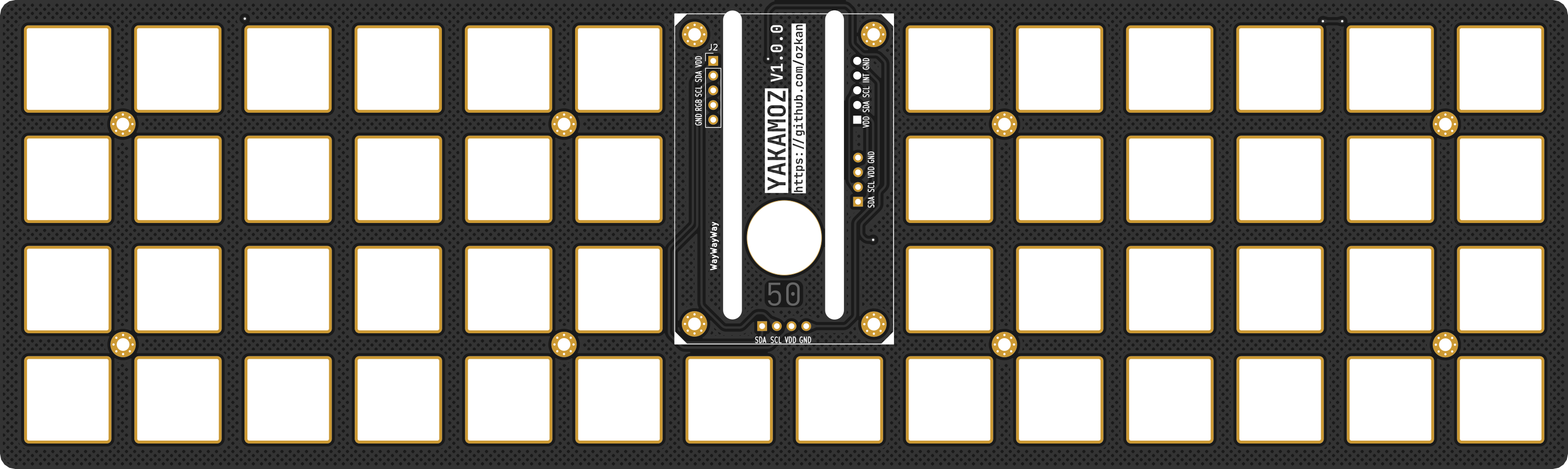
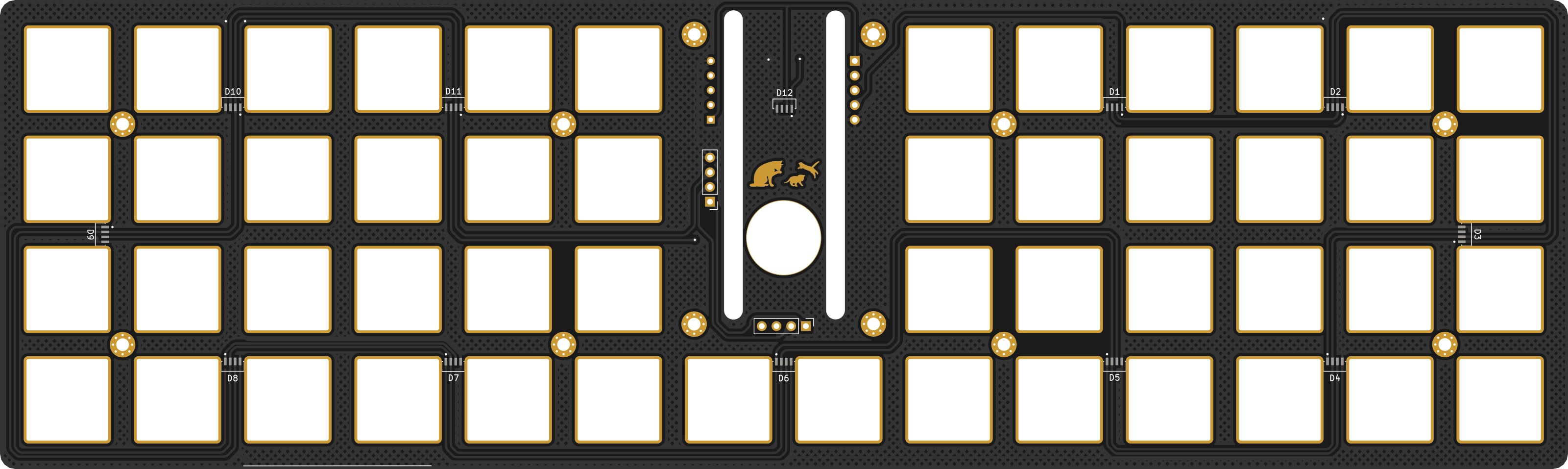
PCB RENDERS
SCHEMATICS
Main Pcb Schematic

Switchplate Schematic

YAKAMOZ BUILD GUIDE
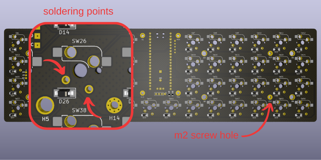
Main PCB Solder Parts On Bottom Side
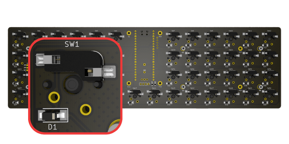
Solder the 50x hot-swap sockets, 50x Sod123 SMD diodes to the pcb bottom side. Solder the diode and hot-swap sockets as shown in the figure above.
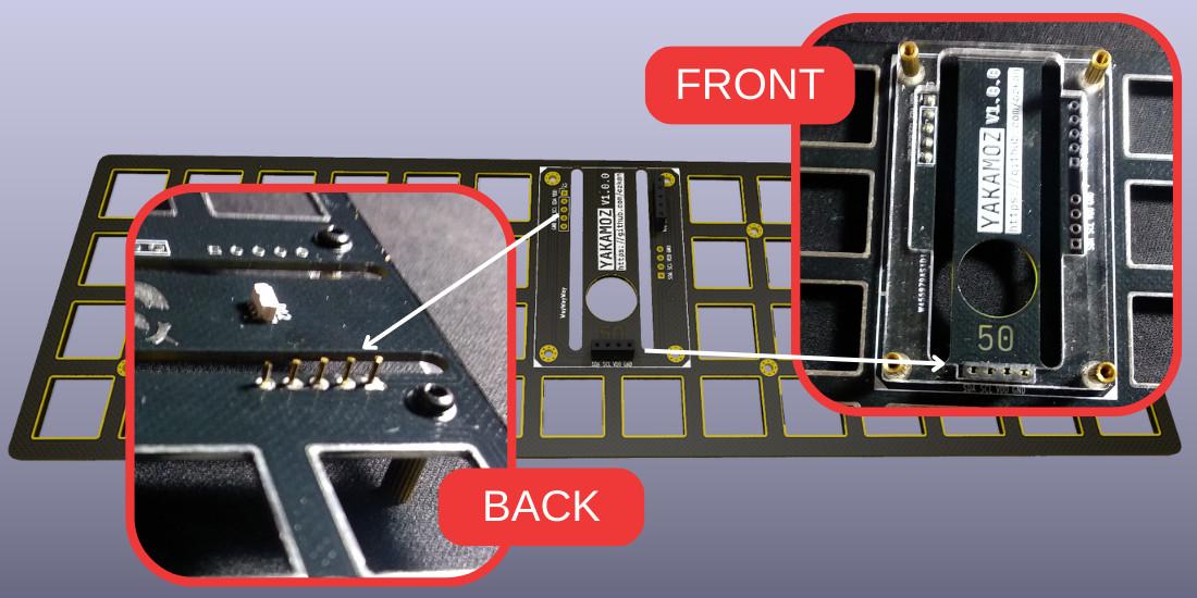
Main PCB Solder Parts On Top Side
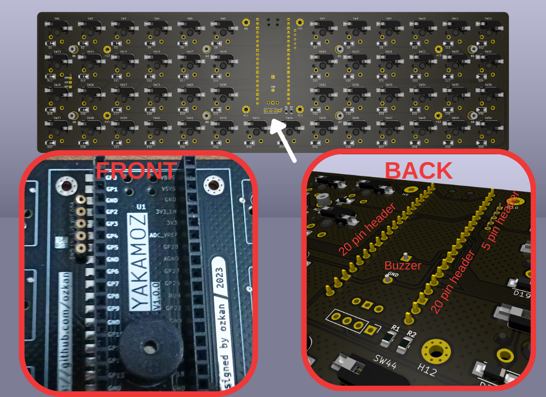
Solder the 2x 20pin single row pin female header (for RPi Pico), single row socket header (Mill-Max Series 315) (for switchplate) and buzzer.
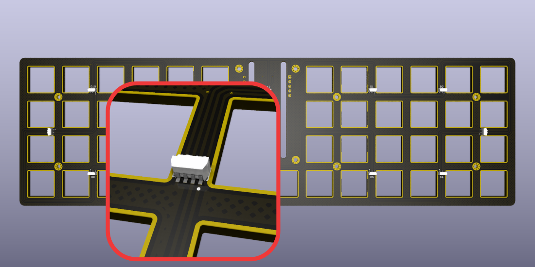
Switchplate PCB Solder Parts On Bottom Side
Acrylic Case File (Sandwich Case)
Download the required dxf files from the link below and get the acrylic plates cut by a laser service according to the specified thickness.
Dxf files: https://github.com/ozkan/Yakamoz/tree/main/Plates

CASE ASSEMBLY
first screw the 7mm spacers to the bottom plate, then build the acrylic case, as shown in the video below. Insert the screws after all the plates are in place.
FINAL ASSEMBLY
Securing the PCB in the case and adding switches and keycaps will complete the assembly.
FIRMWARE
Github repository for YAKAMOZ QMK Firmware : https://github.com/ozkan/Yakamoz-qmk
You can fork my QMK repo which automatically builds firmware through GitHub Actions. Just fork this repository, enable GitHub Actions, and commit and see the firmware build as an artifact.
To Build Firmware In Github Action
- Setup
- Fork this repo.
- Enable GitHub Actions on your fork.
- Build firmware
- Push a commit to trigger the build.
- Download the artifact.
To Ender Flash Mode
- The Pico can receive a new firmware by using the device firmware upgrade mode (DFU). Press the “Bootsel” button when powering the microcontroller and it will enter into DFU mode. In this mode, the microcontroller will expose its flash memory as a thumb drive, you will just need to drop the UF2 file into the drive and the board will write it into its flash.
- Alternatively, if QMK has been loaded, double tap the reset button.
VIA/VIAL
There is a VIA/VIAL compatible firmware available in QMK. With this firmware flashed, the board will be automatically recognised by VIA/VIAL when you plug it in
REDUCE THE COST
Also on this keyboard there are soldering points where you can solder the switches. This way you don’t need to use a switchplate and acrylic centre plates, thus you can reduce the cost.

For the soldered switch version, the locations of the screw holes of the bottom plate are different. You can download the required dxf file from the link below.
Bottom plate for soldered swtitch version
MANUFACTURER
There are a lot of options here. I’ve personally used PCBWay (Referral program link) to great success.
Acknowledgements
PCBWay supports developers to try out creative board designs, thereby enhancing the development of the community and the hobby. Moreover, PCBWay’s boards have high quality, so I highly recommend their services.